- 您现在的位置:买卖IC网 > Sheet目录987 > LD4T06P0 (Red Lion Controls)TIMER 6 DIGIT 4.0" 120VAC RED
�� �
�
�2.0� S� ETTING�
�THE�
�DIP� S� WITCHES�
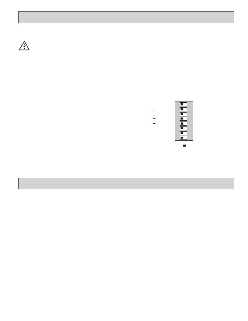
�To� access� the� switches,� remove� the� right� side� plate� of� the� meter.� A� bank� of� eight�
�switches� is� located� inside� the� unit.� Note:� Some� switches� are� not� used� and� should�
�remain� in� the� factory� set� position.�
�Warning� :� Exposed� line� voltage� exists� on� the� circuit� boards.�
�Remove� all� power� to� the� meter� and� load� circuits� before� accessing�
�inside� of� the� meter.�
�SWITCH� 1� (Unused)�
�This� switch� is� not� used� and� should� remain� in� the� factory� set� position.�
�SWITCH� 2� (Input� A)� {See� Note� 1}�
�SNK� :� Adds� internal� 7.8� K� ?� pull-up� resistor� to� +12� VDC,� I� MAX� =� 2.1� mA.�
�SRC� :� Adds� internal� 3.9� K� ?� pull-down� resistor,� 7.2� mA� max.� @� 28� VDC� max.�
�SWITCH� 3� (Input� A)�
�FILTER� ON� :� Provides� hardware� debounce� for� Input� A� to� allow� relay� or�
�switch� contacts� to� be� used� as� a� signal� source.� Software� debounce� for� Inputs�
�A� and� B� is� provided� in� the� programming� menu� (Module� 1).�
�SWITCH� 6� (RESET/USER� INPUT)� {See� Note� 1}�
�SNK� :� Adds� internal� 7.8� K� ?� pull-up� resistor� to� +12VDC,� I� MAX� =� 2.1� mA.�
�SRC� :� Adds� internal� 3.9� K� ?� pull-down� resistor,� 7.2� mA� max.� @� 28� VDC� max.�
�SWITCH� 7� (Unused)�
�This� switch� is� not� used� and� should� remain� in� the� factory� set� position.�
�SWITCH� 8� (Input� B)�
�NORMAL� :� Input� B� performs� the� normal� functions� described� in� the� Timer�
�Input� Operation� parameter� of� the� programming� menu� (Module� 1).�
�INTENSITY� ADJUST� :� In� this� position,� Input� B� is� used� to� adjust� the� LED�
�display� intensity.� Five� distinct� LED� levels� can� be� set� by� pulsing� Input� B.�
�The� display� intensity� level� can� also� be� set� in� the� programming� menu�
�(Module� 3).�
�Note� 1:� When� the� DIP� switch� is� in� the� SNK� position� (OFF),� the� input� is�
�configured� as� active� low.� When� the� switch� is� in� the� SRC� position� (ON),� the�
�input� is� configured� as� active� high.�
�SWITCH� 4� (Input� B)� {See� Note� 1}�
�SNK� :� Adds� internal� 7.8� K� ?� pull-up� resistor� to� +12� VDC,� I� MAX� =� 2.1� mA.�
�SRC� :� Adds� internal� 3.9� K� ?� pull-down� resistor,� 7.2� mA� max.� @� 28� VDC� max.�
�SWITCH� 5� (Input� B)�
�FILTER� ON� :� Provides� hardware� debounce� for� Input� B� to� allow� relay� or�
�Input� A�
�Input� B�
�UNUSED�
�SNK�
�FILTER� OFF�
�SNK�
�FILTER� OFF�
�1�
�2�
�3�
�4�
�5�
�SRC�
�ON�
�SRC�
�ON�
�switch� contacts� to� be� used� as� a� signal� source.� Software� debounce� for� Inputs�
�A� and� B� is� provided� in� the� programming� menu� (Module� 1).�
�Reset/User� Input� SNK�
�UNUSED�
�6�
�7�
�SRC�
�Input� B� Normal�
�8�
�ON�
�Intensity� Adjust�
�Factory� Setting�
�3.0� W� IRING�
�THE�
�M� ETER�
�EMC� INSTALLATION� GUIDELINES�
�Although� this� meter� is� designed� with� a� high� degree� of� immunity� to� Electro-�
�Magnetic� Interference� (EMI),� proper� installation� and� wiring� methods� must� be�
�followed� to� ensure� compatibility� in� each� application.� The� type� of� the� electrical�
�noise,� source� or� coupling� method� into� the� meter� may� be� different� for� various�
�installations.� The� meter� becomes� more� immune� to� EMI� with� fewer� I/O�
�connections.� Cable� length,� routing,� and� shield� termination� are� very� important�
�and� can� mean� the� difference� between� a� successful� or� troublesome� installation.�
�Listed� below� are� some� EMC� guidelines� for� successful� installation� in� an�
�industrial� environment.�
�1.� The� meter� should� be� properly� connected� to� protective� earth.�
�2.� Use� shielded� (screened)� cables� for� all� Signal� and� Control� inputs.� The� shield�
�(screen)� pigtail� connection� should� be� made� as� short� as� possible.� The�
�connection� point� for� the� shield� depends� somewhat� upon� the� application.�
�Listed� below� are� the� recommended� methods� of� connecting� the� shield,� in� order�
�of� their� effectiveness.�
�a.� Connect� the� shield� only� at� the� panel� where� the� unit� is� mounted� to� earth�
�ground� (protective� earth).�
�b.� Connect� the� shield� to� earth� ground� at� both� ends� of� the� cable,� usually� when�
�the� noise� source� frequency� is� above� 1� MHz.�
�c.� Connect� the� shield� to� common� of� the� meter� and� leave� the� other� end� of� the�
�shield� unconnected� and� insulated� from� earth� ground.�
�3.� Never� run� Signal� or� Control� cables� in� the� same� conduit� or� raceway� with� AC�
�power� lines,� conductors� feeding� motors,� solenoids,� SCR� controls,� and�
�heaters,� etc.� The� cables� should� be� ran� in� metal� conduit� that� is� properly�
�grounded.� This� is� especially� useful� in� applications� where� cable� runs� are� long�
�and� portable� two-way� radios� are� used� in� close� proximity� or� if� the� installation�
�is� near� a� commercial� radio� transmitter.�
�3�
�4.� Signal� or� Control� cables� within� an� enclosure� should� be� routed� as� far� as� possible�
�from� contactors,� control� relays,� transformers,� and� other� noisy� components.�
�5.� In� extremely� high� EMI� environments,� the� use� of� external� EMI� suppression�
�devices,� such� as� ferrite� suppression� cores,� is� effective.� Install� them� on� Signal�
�and� Control� cables� as� close� to� the� unit� as� possible.� Loop� the� cable� through� the�
�core� several� times� or� use� multiple� cores� on� each� cable� for� additional� protection.�
�Install� line� filters� on� the� power� input� cable� to� the� unit� to� suppress� power� line�
�interference.� Install� them� near� the� power� entry� point� of� the� enclosure.� The�
�following� EMI� suppression� devices� (or� equivalent)� are� recommended:�
�Ferrite� Suppression� Cores� for� signal� and� control� cables:�
�Fair-Rite� #� 0443167251� (RLC#� FCOR0000)�
�TDK� #� ZCAT3035-1330A�
�Steward� #� 28B2029-0A0�
�Line� Filters� for� input� power� cables:�
�Schaffner� #� FN610-1/07� (RLC#� LFIL0000)�
�Schaffner� #� FN670-1.8/07�
�Corcom� #� 1� VR3�
�Note:� Reference� manufacturer's� instructions� when� installing� a� line� filter.�
�6.� Long� cable� runs� are� more� susceptible� to� EMI� pickup� than� short� cable� runs.�
�Therefore,� keep� cable� runs� as� short� as� possible.�
�7.� Switching� of� inductive� loads� produces� high� EMI.� Use� of� snubbers� across�
�inductive� loads� suppresses� EMI.�
�Snubber:� RLC#� SNUB0000.�
�发布紧急采购,3分钟左右您将得到回复。
相关PDF资料
LFSTBEB7361
BOARD DEV ACCELEROMETER MMA7361L
LFSTBEB7455
BOARD DEV ACCELEROMETER MMA7455L
LFSTBEB8450
BOARD DEV ACCELEROMETER MMA8450
LFSTBEB845X
EVAL BOARD FOR MMA845XQ
LH1518AT
RELAY SSR SPST 250V 300MA 6DIP
LI12-1A79
RELAY REED SPST 1A 12V
LK1AF-24V
RELAY GEN PURPOSE SPST 5A 24V
LKG1AF-24V-16-1
RELAY GEN PURPOSE SPST 16A 24V
相关代理商/技术参数
LD50
制造商:General Tools 功能描述:Deluxe Lightning Detector 制造商:General Tools 功能描述:DETECTOR LIGHTNING
LD-50
制造商:API TECHNOLOGIES 功能描述: 制造商:API Technologies Corp 功能描述:
LD5000
制造商:WTE 制造商全称:Won-Top Electronics 功能描述:50A 10mm LUCAS TYPE PRESS-FIT DIODE
LD5001
制造商:WTE 制造商全称:Won-Top Electronics 功能描述:50A 10mm LUCAS TYPE PRESS-FIT DIODE
LD5002
制造商:WTE 制造商全称:Won-Top Electronics 功能描述:50A 10mm LUCAS TYPE PRESS-FIT DIODE
LD5003
制造商:WTE 制造商全称:Won-Top Electronics 功能描述:50A 10mm LUCAS TYPE PRESS-FIT DIODE
LD5004
制造商:WTE 制造商全称:Won-Top Electronics 功能描述:50A 10mm LUCAS TYPE PRESS-FIT DIODE
LD5005
制造商:WTE 制造商全称:Won-Top Electronics 功能描述:50A 10mm LUCAS TYPE PRESS-FIT DIODE